

 Send Inquiry
Parrallel Resonance Circuit
Parrallel Resonance Circuit Specification
- Measurement Range
- Frequency range dependent on circuit components
- Automation Grade
- Manual
- Feature
- Circulating currents at resonance
- Frequency
- Determined by the values of L and C (Resonance Frequency)
- Voltage
- AC Voltage (Vs)
- Temperature Range
- Dependent on material properties of components
- Accuracy
- High
- Model No
- None
- Power Source
- Voltage Source (AC)
- Core Components
- Resistor (R) Inductor (L) Capacitor (C) Voltage Source (Vs)
- Equipment Materials
- Electrical components (Resistor Inductor Capacitor)
- Type
- Parallel Resonance Circuit
- Usage
- Used in frequency-selective applications like filters and tuning circuits
- Display Type
- None
- Dimension (L*W*H)
- Not applicable for circuit schematic
- Weight
- Dependent on physical components
About Parrallel Resonance Circuit
The Parallel Resonance Circuit is a high-accuracy electrical component assembly used in frequency-selective applications such as filters and tuning circuits. Comprising of a resistor, inductor, capacitor, and voltage source, this circuit facilitates circulating currents at the resonance frequency determined by the values of inductance and capacitance. With manual automation grade and AC voltage source, the circuits temperature range and measurement range are dependent on the material properties and components used. Its weight varies based on the physical components, and the absence of a display type and specific dimensions make it versatile for different applications.
FAQs of Parrallel Resonance Circuit:
Q: What is the primary usage of the Parallel Resonance Circuit?
A: The Parallel Resonance Circuit is primarily used in frequency-selective applications like filters and tuning circuits.Q: What components make up the Parallel Resonance Circuit?
A: The Parallel Resonance Circuit consists of a resistor, inductor, capacitor, and a voltage source.Q: How is the resonance frequency determined in the Parallel Resonance Circuit?
A: The resonance frequency in the Parallel Resonance Circuit is determined by the values of inductance (L) and capacitance (C).Q: What is the power source for the Parallel Resonance Circuit?
A: The power source for the Parallel Resonance Circuit is an AC Voltage Source (Vs).Q: What automation grade does the Parallel Resonance Circuit have?
A: The Parallel Resonance Circuit has a manual automation grade.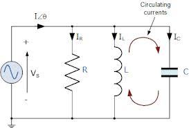
Tell us about your requirement

Price:
Quantity
Select Unit
- 50
- 100
- 200
- 250
- 500
- 1000+
Additional detail
Mobile number
Email

More Products in APPLIED MECHANICS Category
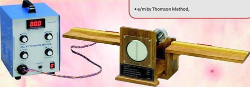
E/M by Thompson Method
Accuracy : 0.1%
Equipment Materials : Brass Aluminum
Core Components : Magnet Scale Power Supply
Type : Experimental Physics Equipment
Dimension (L*W*H) : 150 mm x 100 mm x 200 mm
Usage : Determination of chargetomass ratio using Thompson method

Parallel Forces Apparatus (Tubular spring balance)
Accuracy : Standard
Equipment Materials : Metal and highstrength materials
Core Components : Tubular spring balance rod base
Type : Educational apparatus
Dimension (L*W*H) : Standard dimensions (custom dimensions may vary)
Usage : Used for teaching physics concepts related to forces
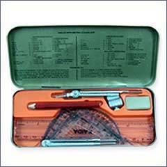
Geometrical Instrument Box
Accuracy : High precision tools for geometrical measurements
Equipment Materials : Plastic and metal
Core Components : Compass Divider Scale Protractor Set Square
Type : Educational instrument box
Dimension (L*W*H) : Standard dimensions as per educational instrument norms
Usage : Used for geometrical drawing and measurements
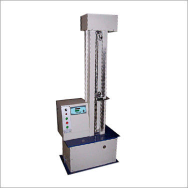
Tensile(Briquette)Testing Machine
Accuracy : 1%
Equipment Materials : Cast Iron, Mild Steel
Core Components : Testing Screw, Scale, Loading Yoke, Weights, Fly Wheel
Type : Manually Operated Mechanical Testing Machine
Dimension (L*W*H) : 720 x 250 x 700 mm
Usage : Tensile Strength Testing of Cement Briquettes
M/S SINGHLA SCIENTIFIC INDUSTRIES
GST : 06AOXPS4632P1ZW
GST : 06AOXPS4632P1ZW
5309/27, PUNJABI MOHALLA, Punjabi MohallaAmbala Cantt - 133001, Haryana, India
Phone :07971191038
|


 |
SINGHLA SCIENTIFIC INDUSTRIES
All Rights Reserved.(Terms of Use) Developed and Managed by Infocom Network Private Limited. |
