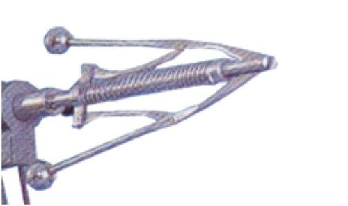
About WATT'S GOVERNOR
Accessory for no. 1988. Shown that the top speed of rotating equipment can be controlled. As the governor is rotated rapidly, the weight attached to the arms spread outward by centrifugal force but are arrested by the two levers as the collar holding the levers rises upward. Demonstration of Speed Regulation via Centrifugal ForceThe Watts Governor illustrates the fundamental principle of speed regulation in engines by utilizing centrifugal force. As the rotational speed changes, governor arms move due to varying centrifugal force, causing the sleeve to adjust and maintain a set speed. This process allows students to visualize and understand mechanical feedback systems in real-time, making laboratory demonstrations both educational and interactive.
Durable Construction and Customizable OptionsWith high-quality materials such as mild steel, brass, steel, and cast iron, the Watts Governor offers dependable performance and resistance to corrosion through its powder-coated or polished finish. Multiple customization options are available for engineering colleges, polytechnics, and laboratory use, ensuring that institutions can tailor the apparatus to their specific educational needs and demonstration methods.
Clear Measurement and Adaptability for Laboratory UseThe governor is fitted with a graduated dial or scale to provide direct speed readings, further enhancing visibility of how operation affects system regulation. Whether driven manually or with an electric motor (compatible with 50/60 Hz supply), instructors can demonstrate the regulation process in ambient laboratory conditions at speeds up to 3000 RPM, covering the essential range for most mechanical demonstrations.
FAQs of WATTS GOVERNOR:
Q: How does the Watts Governor demonstrate speed regulation?
A: It demonstrates speed regulation by using centrifugal force. As the spindle rotates, the governor balls move outward due to increased speed, which in turn raises the sleeve. This adjustment shows how the system maintains a set speed automatically, allowing viewers to observe the mechanical feedback action.
Q: What components are included in a typical Watts Governor setup?
A: A typical setup includes governor arms, balls, a rotating spindle, sleeve, and a stable frame. The apparatus is mounted on a tabletop base plate and utilizes a belt-driven pulley mechanism for operation, operated either manually or by an electric motor.
Q: When is the Watts Governor used in educational settings?
A: The Watts Governor is generally used during laboratory demonstrations in engineering colleges, polytechnics, and technical institutes to teach principles of mechanical speed regulation and control systems.
Q: Where can the Watts Governor be installed or used?
A: This device is designed for tabletop use in laboratories and classroom environments. Its compact size makes it suitable for use on laboratory benches or in demonstration spaces within engineering and technical colleges across India.
Q: What is the process for customizing the Watts Governor to specific requirements?
A: Customization is available by contacting the manufacturer, supplier, or trader. Requirements such as preferred finish, drive type (manual or motorized), and specific dimensions or speed measurement features can be specified to tailor the device for specific educational or demonstration needs.
Q: How does one use the speed indicator on the Watts Governor?
A: Some models feature a dial or graduated scale that shows the rotational speed in real-time. Operators can observe changes in speed and corresponding movement of governor parts, making it easier to study the impact of speed regulation mechanisms.
Q: What benefits do engineering students gain from using the Watts Governor in laboratories?
A: Students gain firsthand experience in understanding mechanical feedback and speed regulation, enhancing analytical skills and practical knowledge. Visible moving parts and adjustable speed components create engaging demonstrations, bridging theoretical concepts with real-world mechanical operation.


 Send Inquiry
