

 Send Inquiry
FORCE ON A CONDUCTOR BALANCE
FORCE ON A CONDUCTOR BALANCE Specification
- Power Source
- 230V AC Power Supply
- Feature
- Highly Efficient
- Frequency
- 50/60 Hz
- Capacity
- 5 Amp
- Accuracy
- 100 %
- Core Components
- Calibrated Balance, Magnetic Coil, Connecting Leads
- Measurement Range
- 0 5A
- Temperature Range
- 0C to 40C
- Automation Grade
- Manual
- Voltage
- 230 V
- Model No
- FOAB-01
- Equipment Materials
- Metal Frame, Non-magnetic Components
- Type
- Force on a Conductor Balance Apparatus
- Usage
- Laboratory
- Dimension (L*W*H)
- 300 x 150 x 180 mm
- Weight
- 2 kg
About FORCE ON A CONDUCTOR BALANCE
Also called Current balance. For demonstration of the relationship between force acting on a current carrying a conductor in a magnetic field. Two metal pillars mounted on an insulated base, each with a 4mm hole for electrical connecting. Conducting arms, consisting of a metal wire shaped into a rectangular L-loop, are mounted on a balance beam, which is supported on the pillar by two conical bearings that act as fulcrum. Two screwed masses are attached to the beam, one horizontally, for adjusting the equilibrium position of the arms, and the other vertically for adjusting the sensitivity. One conducting arm current a rider, which adjust equilibrium with the current flowing by sliding along a scale graduated 0-75 X 1mm. the bend at the end of the conducting arms oscillators vertically in the magnetic field produced by a compound magnet, comprising five identical, horseshoe magnets mounted in the frame. The magnets can slide along a rod mounted on the base with a 6cm scale, giving the length of arms in the magnetic field.Precision Measurement and Efficiency
This apparatus is designed for highly sensitive force measurements on copper conductors within a magnetic field strength up to 0.2 Tesla. Its precision screw adjustment mechanism and finely graduated scale ensure reliable, reproducible results. The inclusion of a factory calibration and overload protection boosts operational confidence while enabling accurate and efficient demonstrations.
Robust Build and User-Friendly Design
Constructed using a durable non-magnetic metal frame with a sleek silver and black powder-coated finish, the equipment combines longevity with aesthetic appeal. Essential accessories like a user manual, power cord, and connecting leads are provided to facilitate effortless setup and operation.
Safe and Compliant Operation
With IS 9001 certification, insulation resistance greater than 100 M, and a maximum test voltage of 250V, this apparatus upholds rigorous safety standards. Overload protection safeguards the equipment during high-current experiments, supporting up to 5A currents and ensuring user and device safety.
FAQs of FORCE ON A CONDUCTOR BALANCE:
Q: How is the FORCE ON A CONDUCTOR BALANCE apparatus used for electromagnetic demonstrations?
A: The apparatus allows you to measure the force exerted on a copper rod by adjusting the current (up to 5 Amps) flowing in the conductor while it is exposed to a magnetic field up to 0.2 Tesla. Observations are made using the precise scale, facilitating vivid demonstrations of electromagnetic force principles in a laboratory setting.Q: What safety features are included in the FOAB-01 model?
A: The apparatus incorporates overload protection to prevent damage during high-current tests, and all components are factory calibrated. It also maintains insulation resistance greater than 100 M and complies with IS 9001 standards for safe laboratory use.Q: When should recalibration of the system be considered?
A: Though the system is factory calibrated, recalibration may be recommended after extensive use, following significant transportation, or annually to maintain the highest measurement accuracy. Refer to the user manual for detailed recalibration procedures.Q: Where can the FORCE ON A CONDUCTOR BALANCE be used?
A: This apparatus is best suited for laboratory environments, educational institutions, and research facilities in India where controlled demonstrations of electromagnetic force on conductors are required. Its tabletop mounting and efficient design support versatile application.Q: What is the process for setting up the equipment for measurements?
A: Place the apparatus on a stable tabletop, connect the supplied power cord, and attach the conductor using the provided leads. Adjust the current through the copper rod and configure the precision screw mechanism for calibration before taking measurements as per the user manual instructions.Q: How does the apparatus benefit laboratory demonstrations?
A: Its high sensitivity, accurate readings (with scale graduations of 10 mg), overload protection, and robust construction make it ideal for reliably illustrating electromagnetic force principles. The highly efficient system saves time and enhances experimental clarity for both students and researchers.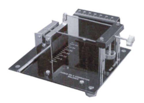
Tell us about your requirement

Price:
Quantity
Select Unit
- 50
- 100
- 200
- 250
- 500
- 1000+
Additional detail
Mobile number
Email

More Products in PHYSICS LABORATORY EQUIPMENT Category
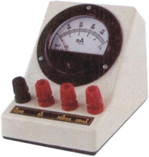
MILLIAMETER, DC
Usage : Research Electronics testing Education
Feature : Measures DC current precisely
Type : Milliammeter
Weight : Approx. 0.5 kg
Dimension (L*W*H) : Approx. 10 cm x 15 cm x 10 cm
Core Components : Analog Meter Terminal Connectors
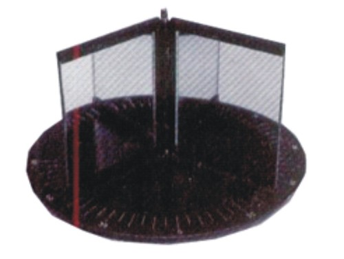
MIRROR, PLANE, ANGULAR
Usage : Laboratory experiments optics demonstration
Feature : Provides clear angular reflection
Type : Angular Plane Mirror
Weight : 500 grams
Dimension (L*W*H) : 30 x 30 x 10 cm
Core Components : Glass Metal Frame

CAREY FOSTER BRIDGE
Usage : Measurement and comparison of low resistances in laboratories
Feature : High precision resistance measurement; sliding jockey contact
Type : Laboratory Bridge
Weight : Approx. 1.5 kg
Dimension (L*W*H) : Approx. 45 cm x 10 cm x 10 cm
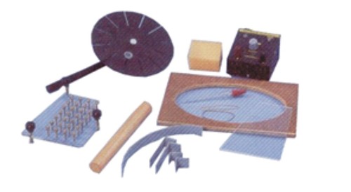
ACCESSORIES FOR RIPPLE TANK
Usage : Educational purposes in wave mechanics
Feature : Used for demonstrating wave properties like reflection refraction and interference
Type : Educational Physics Equipment
Weight : Lightweight for easy handling
Dimension (L*W*H) : Standard dimensions suitable for educational use
Core Components : Ripple Tank Accessories including wave generator and supplementary parts
M/S SINGHLA SCIENTIFIC INDUSTRIES
GST : 06AOXPS4632P1ZW
GST : 06AOXPS4632P1ZW
5309/27, PUNJABI MOHALLA, Punjabi MohallaAmbala Cantt - 133001, Haryana, India
Phone :07971191038
|


 |
SINGHLA SCIENTIFIC INDUSTRIES
All Rights Reserved.(Terms of Use) Developed and Managed by Infocom Network Private Limited. |
